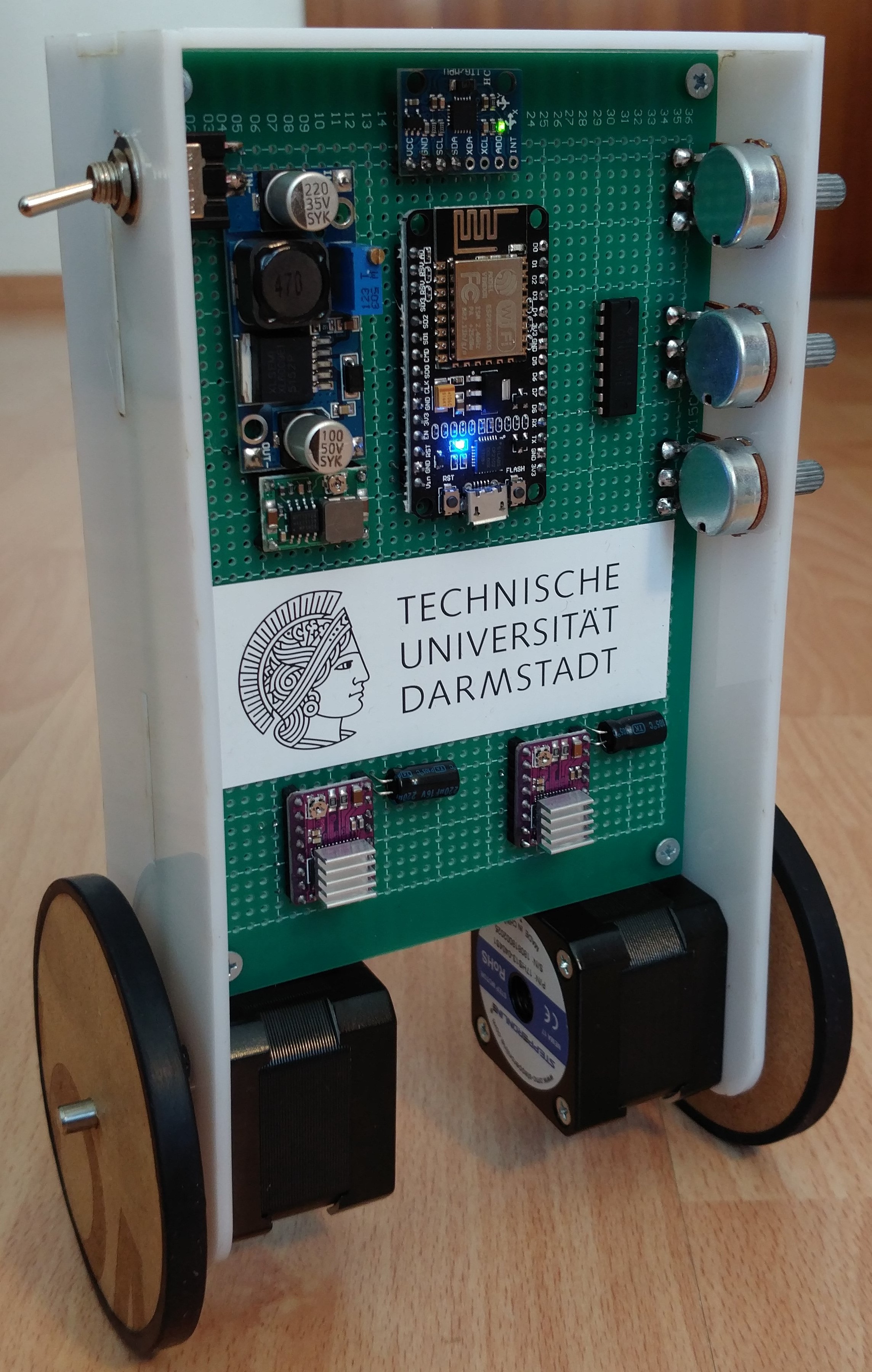
SBRobot
Self balancing Robot
This ESP8266 based Robot is PID controled by an MPU-6050 build up on previous projects thanks to Joop Brokking and Jeff Rowberg. Developed and build by Sven Steinert to represent Industrial Engineering for TU Darmstadt 2019.
Partlist
| QTY | DESCRIPTION | PART NAME |
|---|---|---|
| 1 | Microcontrollerboard | NodeMCU v3.2 ESP8266 Dev Kit WIFI Lolin Amica CP2102 |
| 1 | Gyroscope | GY-521 MPU-6050 |
| 2 | Stepper Motor | Nema 17 34mm 26Ncm 12V 0.4A |
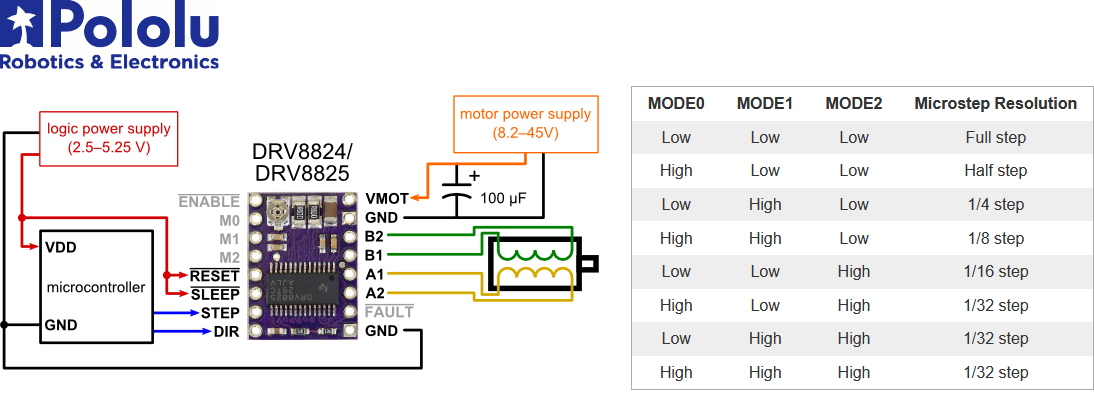
| 2 | Stepper Motor Driver | DRV8825 |
| 2 | Capacitor | 100µF 16V |
| 1 | Boost Modul Step Up | XL6009 DC-DC 3.5V-32V 3A |
| 1 | Buck Step Down | XD-45 MH mini 360 DC-DC LM2596 |
| 4 | Battery | Samsung INR18650-35E 3450mAh 3.7V |
| 1 | Multiplexer | 74HC4051 8-Channel Analog / Digital DIP16 |
| 3 | Potentiometer | 10kΩ Linear Mono |
| 1 | Battery Holder | 4x 18650 82x85x26mm |
| 1 | Battery Charger | NiteCore Digicharger D4 |
| 1 | Switch | 2 Position Toggle Switch |
| 1 | PCB | 10x15 cm Circuit Board |
| 1 | Case | PMMA 3mm |
| 4 | PCB Screw | M3 Flat Head 16mm |
| 8 | Motor Screws | M3 Flat Head 10mm |
| 3 | Battery Screws | M3 Flat Head 12mm |
| 7 | Screw Nuts | M3 Full Nut |
| 2 | Wheel | MDF 6mm |
| 2 | Rubber | Cut Bicycle Tube |
| 1 | Remote Microcontroller | D1 Mini ESP8266 Wifi Nodemcu Modul |
| 1 | Remote | Nunchuk Controller for Nintendo Wii |
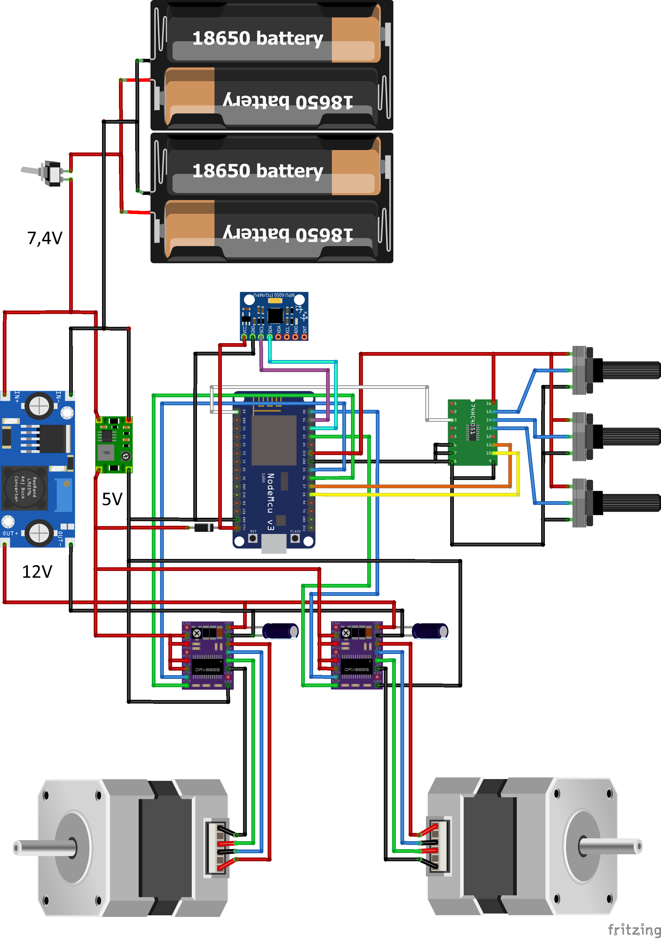
Wiring
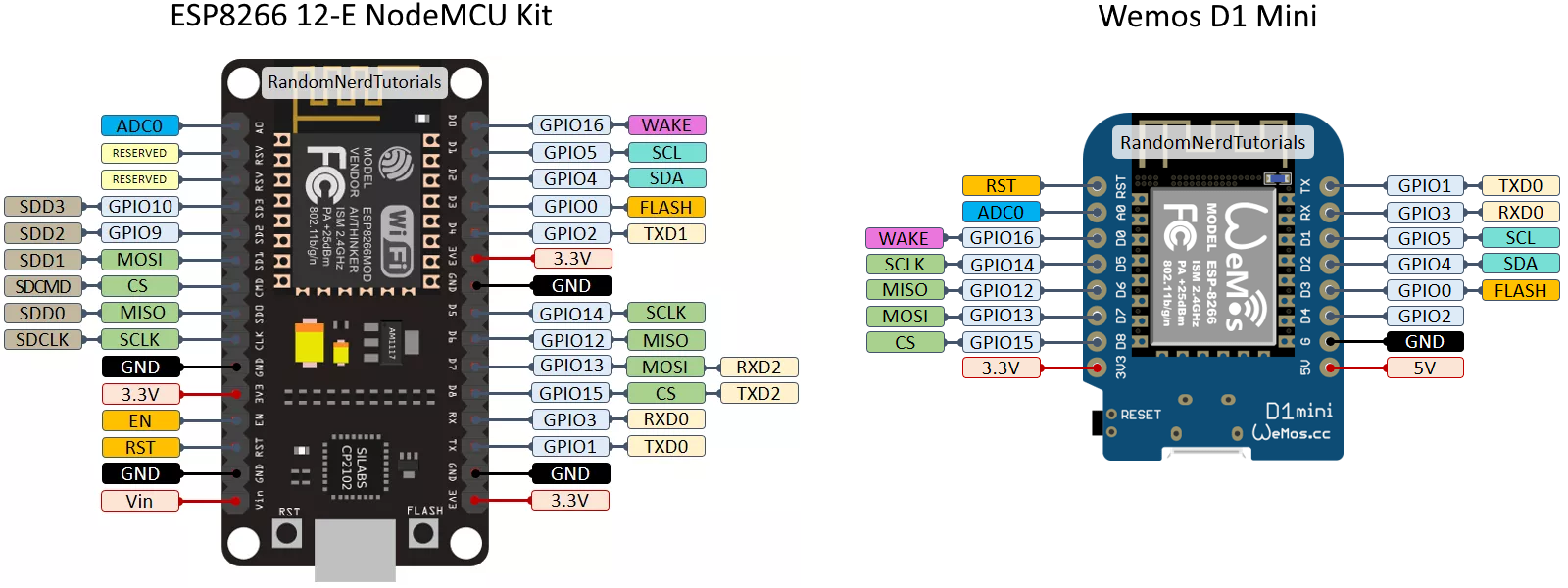
Pinout
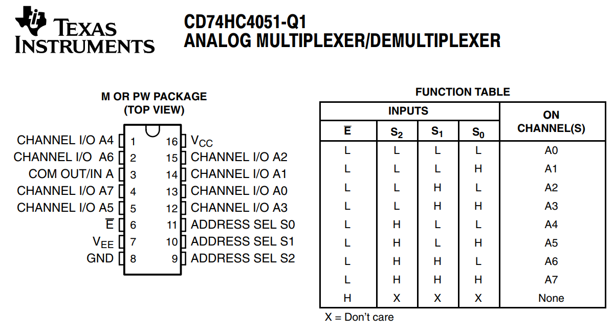
Datasheets
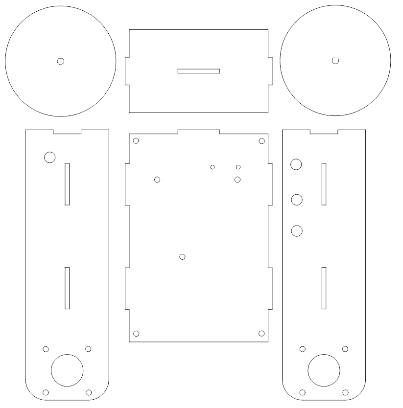
Case
I was using a lasercutter to cut the template out of the PMMA and MDF. Here is the preview of the case.cdr
Comments
The MPU-6050 comes with an individual offset that can be found with this code https://github.com/jrowberg/i2cdevlib/blob/master/Arduino/MPU6050/examples/IMU_Zero/IMU_Zero.ino The PID values are depending on system atttributes like mass or center of mass which wont be exactly the same. The individual settings are signed by the Name of the 2 Robots i made named Ella and Sören. So you have to insert your values there.